This section provides information on the encoding of the acquisition geometry in a fixed reference system.
The operator identifies the position of an object of interest projected on the stored pixel data of an image A, and estimates the magnification of the conic projection by a calibration process.
The operator wants to know the position of the projection of such object of interest on a second image B acquired under different geometry, assuming that the patient does not move between image A and image B (i.e., the images share the same frame of reference).
The XA SOP Class encodes the information in a patient-related coordinate system.
The Enhanced XA SOP Class additionally encodes the geometry of the acquisition system with respect to a fixed reference system defined by the manufacturer, so-called Isocenter reference system. Therefore, it allows encoding the absolute position of an object of interest and to track the projection of such object across the different images acquired under different geometry.
This section provides detailed recommendations of the key attributes to address this particular scenario.
Table FFF.2.5-1. Enhanced X-Ray Angiographic Image IOD Modules
|
IE |
Module |
PS3.3 Reference |
Usage |
|---|---|---|---|
|
Image |
Image Pixel |
C.7.6.3 |
Specifies the dimension of the pixel array of the frames. |
|
XA/XRF Acquisition |
C.8.19.3 |
Describes some characteristics of the acquisition system that enables this scenario. |
|
|
X-Ray Detector |
C.8.19.5 |
Specifies the type and characteristics of the image detector. |
Table FFF.2.5-2. Enhanced XA Image Functional Group Macros
|
Functional Group Macro |
PS3.3 Reference |
Usage |
|---|---|---|
|
X-Ray Field of View |
C.8.19.6.2 |
Specifies the dimension of the Field of View as well as the flip and rotation transformations. |
|
X-Ray Isocenter Reference System |
C.8.19.6.13 |
Specifies the acquisition geometry in a fixed reference system. |
|
X-Ray Geometry |
C.8.19.6.14 |
Specifies the distances of the conic projection. |
|
XA/XRF Frame Pixel Data Properties |
C.8.19.6.4 |
Specifies the dimensions of the pixels at the image reception plane. |
The usage of this module is recommended to specify the number of rows and columns of the Pixel Data, as well as the aspect ratio.
The usage of this module is recommended to give the necessary conditions to enable the calculations of this scenario.
Table FFF.2.5-3. XA/XRF Acquisition Module Recommendations
|
Attribute Name |
Tag |
Comment |
|---|---|---|
|
X-Ray Receptor Type |
(0018,9420) |
DIGITAL_DETECTOR is used in this scenario. |
|
Positioner Type |
(0018,1508) |
CARM is used in this scenario. |
|
C-arm Positioner Tabletop Relationship |
(0018,9474) |
YES is necessary in this scenario. |
In case of X-Ray Receptor Type (0018,9420) equals "IMG_INTENSIFIER", there are some limitations that prevent the calculations described on this scenario:
-
The position of the projection of the isocenter on the intensifier active area is undefined;
-
The Field of View Origin (0018,7030) cannot be related to the physical area of the receptor because the Intensifier TLHC is undefined.
As a consequence, in case of image intensifier it is impossible to relate the position of the pixels of the stored area to the isocenter reference system.
In case of X-Ray Receptor Type (0018,9420) equals "DIGITAL_DETECTOR" the usage of this module is recommended to specify the type and characteristics of the image detector.
The usage of this macro is recommended to specify the characteristics of the field of view.
The field of view characteristics may change per-frame across the multi-frame image.
The usage of this macro is recommended to specify the fixed reference system of the acquisition geometry.
The usage of this macro is recommended to specify the distances between the X-Ray source, isocenter and X-Ray detector.
In this example, the operator identifies the position (i, j) of an object of interest projected on the stored pixel data of an image A, and estimates the magnification of the conic projection by a calibration process.
The operator wants to know the position of the projection of such object of interest on a second image B acquired under different geometry.
The attributes that define the geometry of both images A and B are described in the following figure:

The following steps describe the process to calculate the position (i, j)B of the projection of the object of interest in the Pixel Data of the image B, assuming that (i, j)A is known and is the offset of the projection of the object of interest from the TLHC of the Pixel Data of the image A, measured in pixels of the Pixel Data matrix as a column offset "i" followed by a row offset "j". TLHC is defined as (0,0).
Step 1: Calculate the point (i, j)A in FOV coordinates of the image A.
Step 2: Calculate the point (i, j)A in physical detector coordinates of the image A.
Step 3: Calculate the point (Pu, Pv)A in positioner coordinates of the image A.
Step 4: Calculate the point (PXp, PYp, PZp)A in positioner coordinates of the image A.
Step 5: Calculate the point (PX, PY, PZ)A in Isocenter coordinates of the image A.
Step 6: Calculate the point (PXt, PYt, PZt)A in Table coordinates of the image A.
Step 7: Calculate the point (PXt, PYt, PZt)B in Table coordinates in mm of the image B.
Step 8: Calculate the point (PX, PY, PZ)B in Isocenter coordinates in mm of the image B.
Step 9: Calculate the point (PXp, PYp, PZp)B in positioner coordinates of the image B.
Step 10: Calculate the point (Pu, Pv)B in positioner coordinates of the image B.
Step 11: Calculate the point (i, j)B in physical detector coordinates of the image B.
Step 12: Calculate the point (i, j)B in FOV coordinates of the image B.
Step 13: Calculate the point (i, j)B in Pixel Data of the image B.
In this example let's assume:
(i, j)A = (310,122) pixels
Magnification ratio = 1.3
Step 1 : Image A: Point (i, j)A in FOV coordinates
In this step, the FOV coordinates are calculated by taking into account the FOV rotation and Horizontal Flip applied to the FOV matrix when the Pixel Data were created:
1.1: Horizontal Flip : YES
new i = (columns -1) - i = 850 - 1 - 310 = 539
new j = j = 122
1.2: Image Rotation : 90 (clockwise)
new i = j = 122
new j = (columns -1) - i = 850 - 1 - 539 = 310
(i, j)A = (122, 310) in stored pixel data.
Step 2: Image A: Point (i, j)A in physical detector coordinates
In this step, the physical detector coordinates are calculated by taking into account the FOV origin and the ratio between Imager Pixel Spacing and Detector Element Spacing:
Di = Imager Pixel Spacing (column) = 0.2 mm
Dj = Imager Pixel Spacing (row) = 0.2 mm
Didet = Detector Element Spacing between two adjacent columns = 0.2 mm
Djdet = Detector Element Spacing between two adjacent rows = 0.2 mm
Zoom Factor (column) = Di / Didet = 1.0
Zoom Factor (row) = Dj / Djdet = 1.0
FOV Origin (column) = FOVidet = 600.0
FOV Origin (row) = FOVjdet = 600.0
new i = FOVidet + (i + (1 - Didet / Di) / 2) * Dj / Djdet = 600 + 122 * 1.0 = 722
new j = FOVjdet + (j + (1 - Djdet / Dj) / 2) * Di / Didet = 600 + 310 * 1.0 = 910
(i, j)A = (722, 910) in detector elements.
Step 3: Image A: Point ( Pu, Pv)A in positioner coordinates
In this step, the (Pu, Pv)A coordinates in mm are calculated from (i, j)A by taking into account the projection of the Isocenter in physical detector coordinates, and the Detector Element Spacing:
ISO_Pidet = Position of Isocenter Projection (column) = 1024.5
ISO_Pjdet = Position of Isocenter Projection (row) = 1024.5
Didet = Detector Element Spacing between two adjacent columns = 0.2 mm
Djdet = Detector Element Spacing between two adjacent rows = 0.2 mm
Pu = (i - ISO_Pidet) * Didet = (722 - 1024.5) * 0.2 = -60.5 mm
Pv = (ISO_Pjdet - j) * Djdet = (1024.5 - 910) * 0.2 = 22.9 mm
( Pu, Pv)A = (-60.5, 22.9) in mm.
Step 4: Image A: Point (PXp, PYp, PZp)A in positioner coordinates
In this step, the positioner coordinates (PXp, PYp, PZp)A are calculated from (Pu, Pv)A by taking into account the magnification ratio, the Distance Source to Detector and the Distance Source to Isocenter:
SID = Distance Source to Detector = 1300 mm
ISO = Distance Source to Isocenter = 780 mm
Magnification ratio = SID / (ISO - P Yp ) = 1.3
P Yp = ISO - SID / 1.3 = 780 - 1300/1.3 = -220 mm
P Xp = Pu / Magnification ratio = -60.5 / 1.3 = -46.54 mm
P Zp = Pv / Magnification ratio = 22.9 / 1.3 = 17.62 mm
(PXp, PYp, PZp)A = (-46.54, -220, 17.62) in mm.
Step 5: Image A: Point (PX, PY, PZ)A in Isocenter coordinates
In this step, the isocenter coordinates (PX, PY, PZ)A are calculated from the positioner coordinates (PXp, PYp, PZp)A by taking into account the positioner angles of the image A in the Isocenter coordinate system:
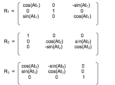
Ap1 = Positioner Isocenter Primary Angle = 60.0 deg
Ap2 = Positioner Isocenter Secondary Angle = 20.0 deg
Ap3 = Positioner Isocenter Detector Rotation Angle = 0.0 deg
(PX, PY, PZ)T= (R2 ·R1)T·(R3 T·(PXp, PYp, PZp)T)
(PX, PY, PZ)A = (150.55, -65.41, 91.80) in mm.
Step 6: Image A: Point (PXt, PYt, PZt)A in Table coordinates
In this step, the table coordinates (PXt, PYt, PZt)A are calculated from the isocenter coordinates (PX, PY, PZ)A by taking into account the table position and angles of the image A in the Isocenter coordinate system:
Tx =Table X Position to Isocenter = 10.0 mm
Ty =Table Y Position to Isocenter = 30.0 mm
Tz =Table Z Position to Isocenter = 100.0 mm
At1 = Table Horizontal Rotation Angle = -10.0 deg
At2 = Table Head Tilt Angle = 0.0 deg
At3 = Table Cradle Tilt Angle = 0.0 deg
(PXt, PYt, PZt)T= (R3 · R2 · R1) · ((PX, PY, PZ)T- (TX, TY, TZ)T)
(PXt, PYt, PZt)A = (136.99, -95.41, -32.48) in mm.
Step 7: Image B: Point (PXt, PYt, PZt)B in Table coordinates
In this step, the table has moved from image A to image B. The table coordinates of the object of interest are the same on image A and image B because it is assumed that the patient is fixed on the table.
(PXt, PYt, PZt)B = (136.99, -95.41, -32.48) in mm.
Step 8: Image B: Point (PX, PY, PZ)B in Isocenter coordinates
In this step, the isocenter coordinates (PX, PY, PZ)B are calculated from the table coordinates (PXt, PYt, PZt)B by taking into account the table position and angles of the image B in the Isocenter coordinate system:
Tx =Table X Position to Isocenter = 20.0 mm
Ty =Table Y Position to Isocenter = 100.0 mm
Tz =Table Z Position to Isocenter = 0.0 mm
At1 = Table Horizontal Rotation Angle = 0.0 deg
At2 = Table Head Tilt Angle = 10.0 deg
At3 = Table Cradle Tilt Angle = 0.0 deg
(PX, PY, PZ)T= (R3 · R2 · R1)T· (PXt, PYt, PZt)T+ (TX, TY, TZ)T
(PX, PY, PZ)B = (156.99, -12.11, -48.55) in mm.
Step 9: Image B: Point (PXp, PYp, PZp)B in positioner coordinates
In this step, the positioner coordinates (PXp, PYp, PZp)B are calculated from the isocenter coordinates (PX, PY, PZ)B by taking into account the positioner angles of the image B in the Isocenter coordinate system:
Ap1 = Positioner Isocenter Primary Angle = -30.0 deg
Ap2 = Positioner Isocenter Secondary Angle = 0.0 deg
Ap3 = Positioner Isocenter Detector Rotation Angle = 0.0 deg
(PXp, PYp, PZp)T= R3 · ((R2 · R1) · (PX, PY, PZ)T)
(PXp, PYp, PZp)B = (142.01, 68.00, -48.55) in mm.
Step 10: Image B: Point ( Pu, Pv)B in positioner coordinates
In this step, the (Pu, Pv)B coordinates in mm are calculated from the positioner coordinates (PXp, PYp, PZp)B by taking into account the Distance Source to Detector and the Distance Source to Isocenter of the image B:
SID = Distance Source to Detector = 1000 mm
ISO = Distance Source to Isocenter = 800 mm
Magnification ratio = SID / (ISO - P Yp ) = 1200/(800-68) = 1.366
Pu = P Xp * Magnification ratio = 142.01 * 1.64 = 194.00 mm
Pv = P Z p * Magnification ratio = -48.55 * 1.64 = -66.33 mm
( Pu, Pv)B = (194.00, -66.33) in mm.
Step 11: Image B: Point (i, j)B in physical detector coordinates
In this step, the physical detector coordinates (i, j)B are calculated from the positioner coordinates ( Pu, Pv)B by taking into account the projection of the Isocenter in physical detector coordinates, and the Detector Element Spacing of the image B:
ISO_Pidet = Position of Isocenter Projection (column) = 1024.5
ISO_Pjdet = Position of Isocenter Projection (row) = 1024.5
Didet =Detector Element Spacing between two adjacent columns = 0.2
Djdet =Detector Element Spacing between two adjacent rows = 0.2
i = ISO_Pidet + Pu / Didet = 1024.5 + 194.00 / 0.2 = 1994.5
j = ISO_Pidet - Pv / Didet = 1024.5 - (-66.33) / 0.2 = 1356.2
(i, j)B = (1994.5, 1356.2) in detector elements.
Step 12 : Image B: Point (i, j)B in FOV coordinates
In this step, the FOV coordinates are calculated from the physical detector coordinates by taking into account the FOV origin and the ratio between Imager Pixel Spacing and Detector Element Spacing of the image B:
Di = Imager Pixel Spacing (column) = 0.4 mm
Dj = Imager Pixel Spacing (row) = 0.4 mm
Didet = Detector Element Spacing between two adjacent columns = 0.2 mm
Djdet = Detector Element Spacing between two adjacent rows = 0.2 mm
Zoom Factor (column) = Di / Didet = 2.0
Zoom Factor (row) = Dj / Djdet = 2.0
FOV Origin (column) = FOVidet = 25.0
FOV Origin (row) = FOVjdet = 25.0
new i = (i - FOVidet).Didet / Di - (1 - Didet / Di) / 2 = (1994.5 - 25.0) / 2.0 - 0.25 = 984.5
new j = (j - FOVjdet).Djdet / Dj - (1 - Djdet / Dj) / 2 = (1356.2 - 25.0) / 2.0 - 0.25 = 665.35
(i, j)B = (984.50, 665.35) in stored pixel data.
Step 13 : Image B: Point (i, j)B in Pixel Data
In this step, the position (i, j)B of the projection of the object of interest in the Pixel Data of the image B is calculated from the FOV coordinates by taking into account the FOV rotation and Horizontal Flip applied to the FOV matrix when the Pixel Data were created:
1.1: Horizontal Flip : NO
new i = i = 984.50
new j = j = 665.35
1.2: Image Rotation : 180 (clockwise)
new i = (columns -1) - i = 1000 - 1 - 984.50 = 14.50
new j = (rows -1) - j = 1000 - 1 - 665.35 = 333.65
(i, j)B = (14.50, 333.65) in stored pixel data.